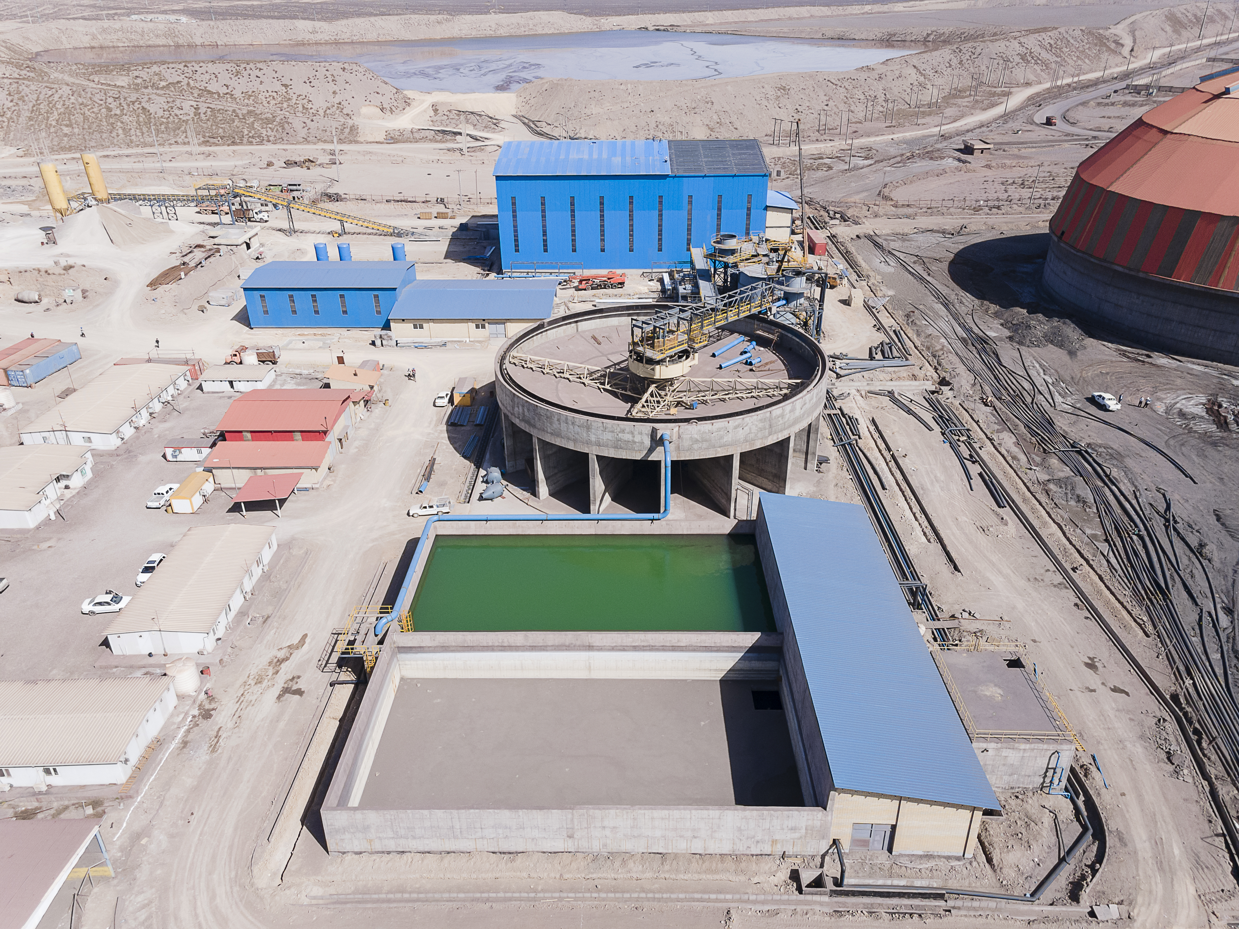
Conventional Thickeners are generally incorporated in heavy duty applications when the underflow density is high and substantial torques are required to convey the settled solids from the periphery to the central outlet for pumping away. Likewise, thickeners are often used for storage to facilitate the continuous feeding of downstream filters or centrifuges. Historically thickeners were introduced to the mining industry in 1905 when the beatification of ores by froth flotation was invented in Australia. In 1964 there was a project to reprocess the huge piles of tailing that accumulated over the years and recover the remaining copper. At that time I was employed by Eimco in Salt Lake City, Utah and participated in a team that conducted test work checking the suitability of large diameter thickeners for both concentrate and tailing of the reprocessed ore.
Basically there are two groups of thickeners which differ in their rake driving mechanisms:
1.Centrally driven
2.Peripherally driven
The following tree shows the two main thickener groups and their various configurations:
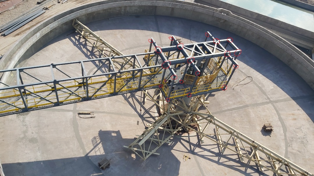
There are two methods of supporting the heavy drive with its shaft and raking arms:
In the bridge type a structure spans across the tank and is subjected vertically to the weight of the mechanism plus any solids that accumulate within the arms truss and horizontally to the twin forces imposed by the density of the raked underflow.
In the column type a central steel or concrete column takes vertically the reaction to the weight of the mechanism and horizontally the torque load.
There is a rule of thumb as to the break even between bridge type and column type mechanisms. For tanks up to 25-30 meter diameter the former type is selected and for larger diameters the later type. However, in many instances other considerations determine the selection such as the local cost of steel versus concrete. Also selection may be influenced by process consideration such as the handling of the dense underflow through a central discharge cone, as in the bridge type, or in a circular trough as in the column type thickeners.
The drive head, together with the raking arms, are the heart of the mechanism since the entire operation of the thickener depends on their ability to convey continuously the dense underflows from the periphery of the tank to the center. Hence, they are always of a robust design to meet the most difficult duties such as metallurgical, potash or phosphate applications where densities may reach 55-60% solids by weight.
Another important factor is reliability since unlike many other types of equipment, thickeners have no stand-bys so if one goes out of commission it cannot be by-passed. Consequently, if this happens other thickeners have to take the extra load but if the plant incorporates just one thickener then the entire production line must stop. Likewise, to take a thickener out of commission for internal repairs such as repair of damaged blades, or rubber lining may take days since it requires to empty the tank, wash out with hoses the underflow bed, refill the tank and find a suitable storage or disposal site for the very large volumes of liquid.
The majority of the drive heads are mechanically driven however hydraulically driven units are also in use.
Typical bridge type drive heads for small thickeners consist of a worm gear as shown on top and for larger units spur gears as may be seen at the bottom. The drives are always mounted directly on the bridge.
The drive head below is designed for column type thickeners. The main gear consists of a rim with internally machined teeth so that the space in the center is left free for a post that is bolted to the top of the column and supports the walkway. It should be noted that the structure that spans radially on a column type thickener is not subjected to any operational load and serves merely as the inner support for the walkway.
Drive heads for both bridge and column type thickeners may be driven by up to 4 electric motors of hi-slip design which can reach 5-8 percent slip without loss of power nor overheating. This special design is required to ensure that the load on the main gear is balanced so that each primary reducer, and subsequently the entire reduction train, is subjected to an equal strain.
The torque capability of a thickener drive is specified as Duty Rating being the maximum mechanism design strength or the 100% setting on the Torque Control Box. The torque, in turn, depends on a K factor and the thickener diameter based on the following formula:
Torque (in Nm) = 14.6*K*D2 (in meters)
The following table specifies the K factors for different Duty Ratings:
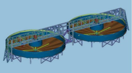

In general terms the type of thickener and its drive torque rating ranges between the following values:

© Copyright 2023 MINTEC All Rights Reserved.
